
Continuous Drying with Vibration-Assisted Fluidization
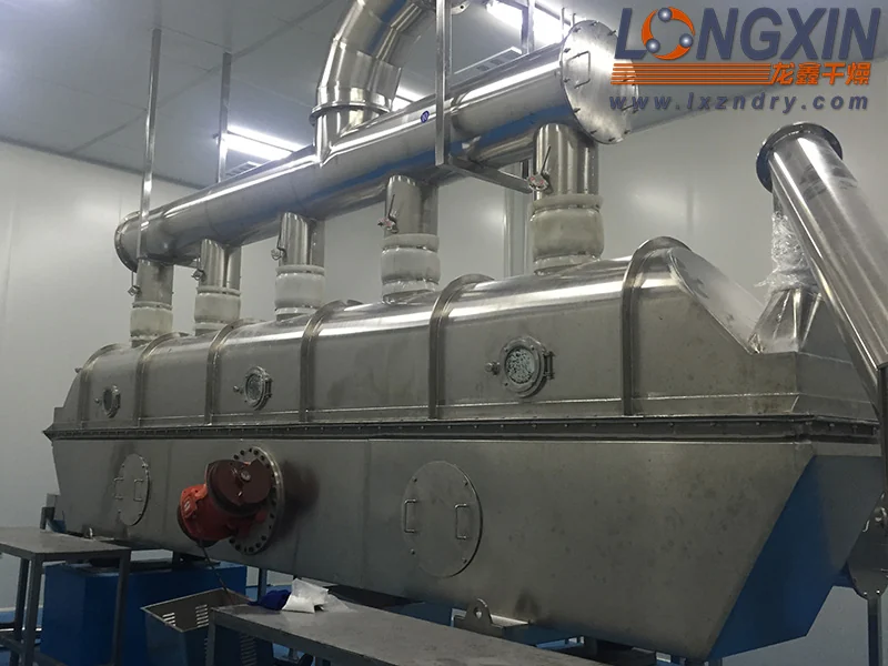
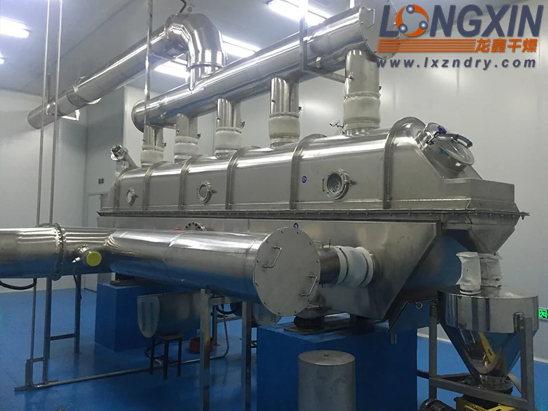
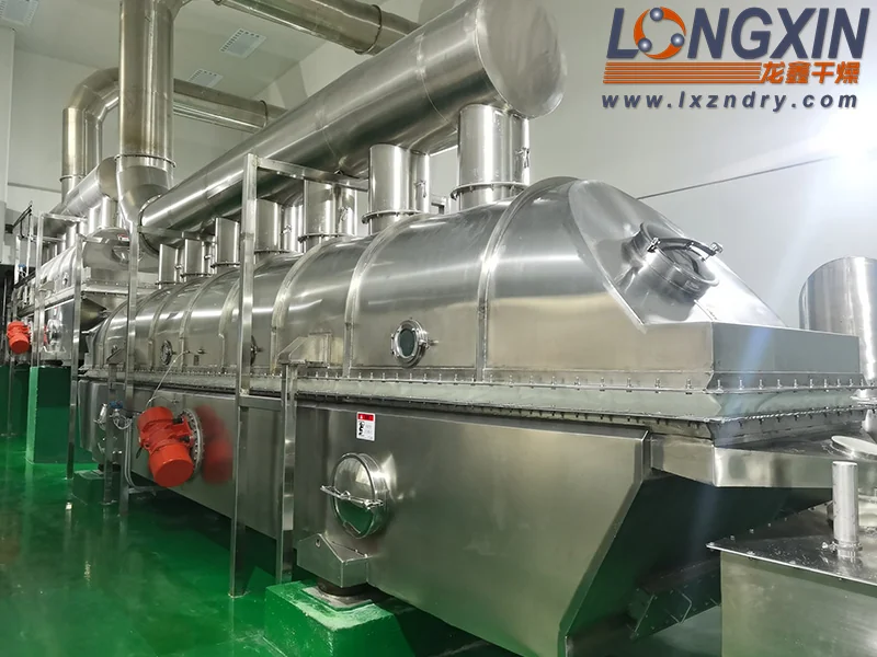
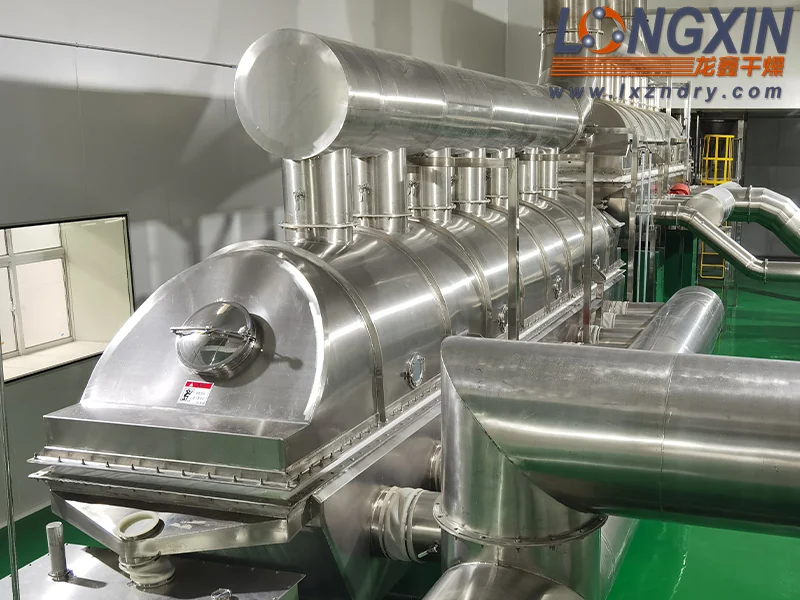
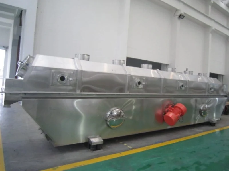
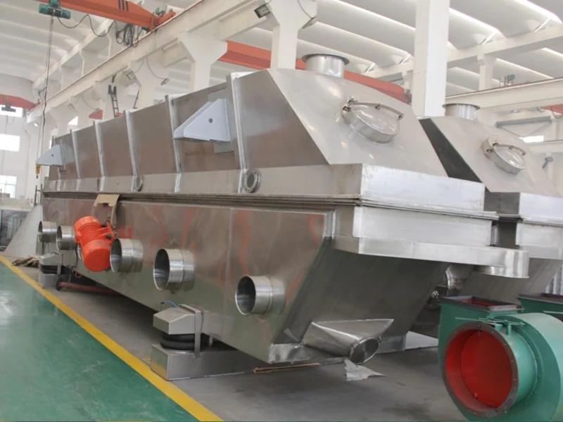
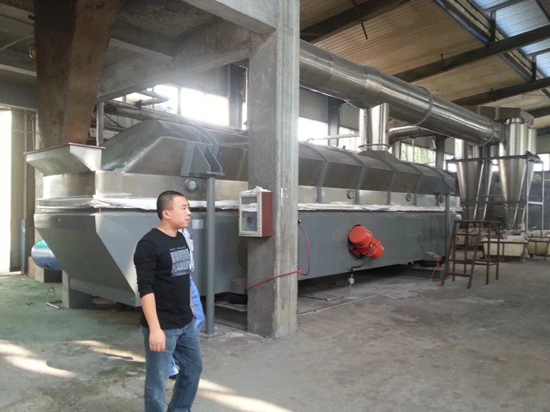
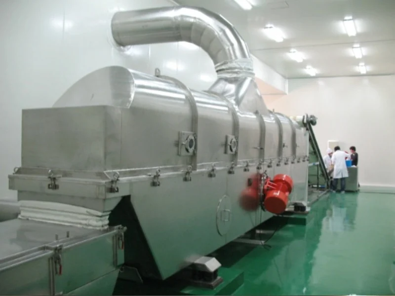
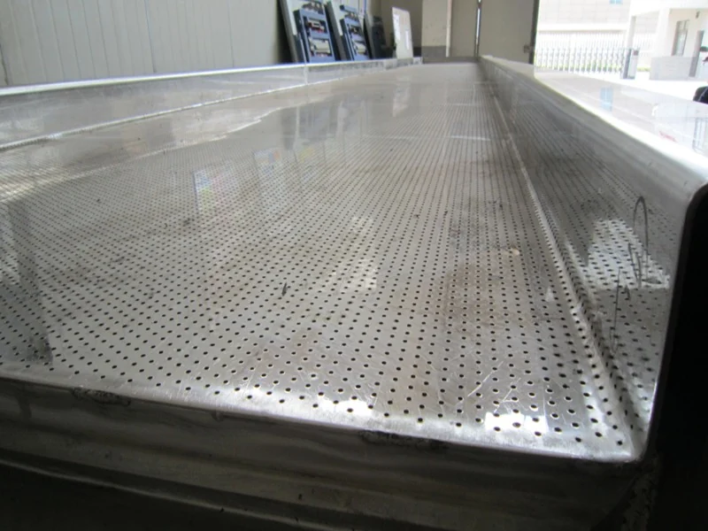
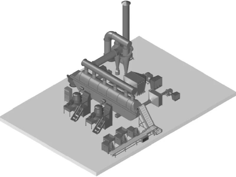
The ZLG vibrating fluid bed dryer uses mechanical vibration to assist fluidization and move material along an air distributor plate. Hot air passes upward through the plate and contacts the particles, providing the heat and mass transfer required for moisture removal.
By adjusting vibration parameters, the system can reduce back-mixing and promote flow closer to plug flow. This helps improve moisture uniformity and disperse materials that tend to agglomerate or form channels in a conventional fluid bed.
How It Works
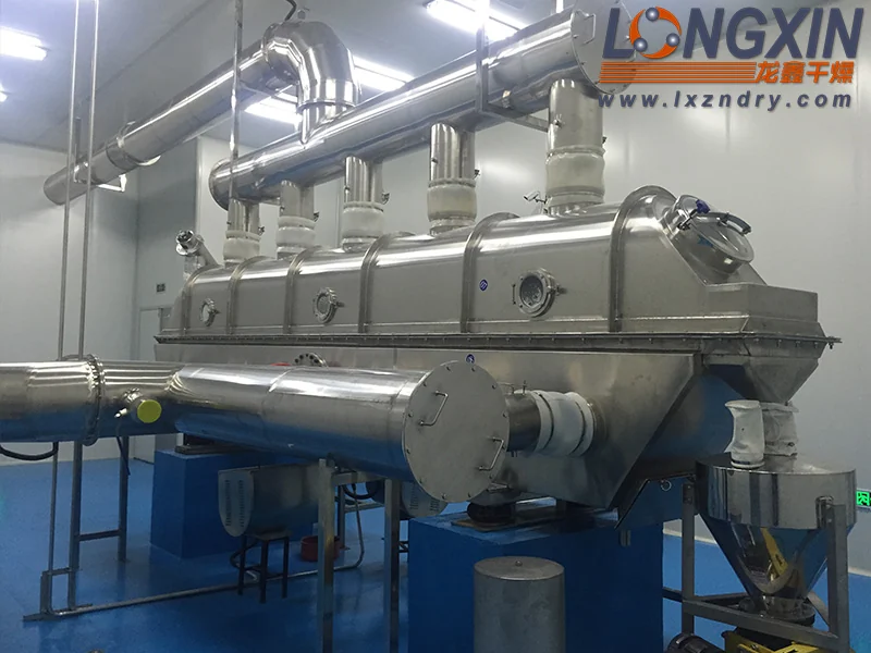
- Air distribution: a fan supplies heated air to the lower plenum. The distributor plate spreads the air across the material bed.
- Vibration-assisted fluidization: vibration loosens and advances the particles while the upward airflow supports fluidization. This can reduce the minimum fluidization velocity compared with a conventional fluid bed.
- Controlled drying: contact between the particles and hot air evaporates moisture. Vibration settings help control material residence time.
- Exhaust removal: the induced-draft fan maintains slight negative pressure above the bed and carries moisture-laden air to the specified exhaust-treatment equipment.
- Product discharge: dried material leaves the bed for collection, cooling, screening or further processing, according to the selected arrangement.
Process Benefits
- Lower airflow demand: vibration-assisted fluidization can reduce the air velocity needed to handle suitable materials and limit fines entrainment.
- Adjustable residence time: vibration settings influence material movement, helping match the drying time to the feed.
- Improved bed uniformity: vibration helps disperse particles and reduce agglomeration and channeling.
- Gentle particle handling: reduced back-mixing and lower gas velocity can limit particle damage where crystal shape or surface quality matters.
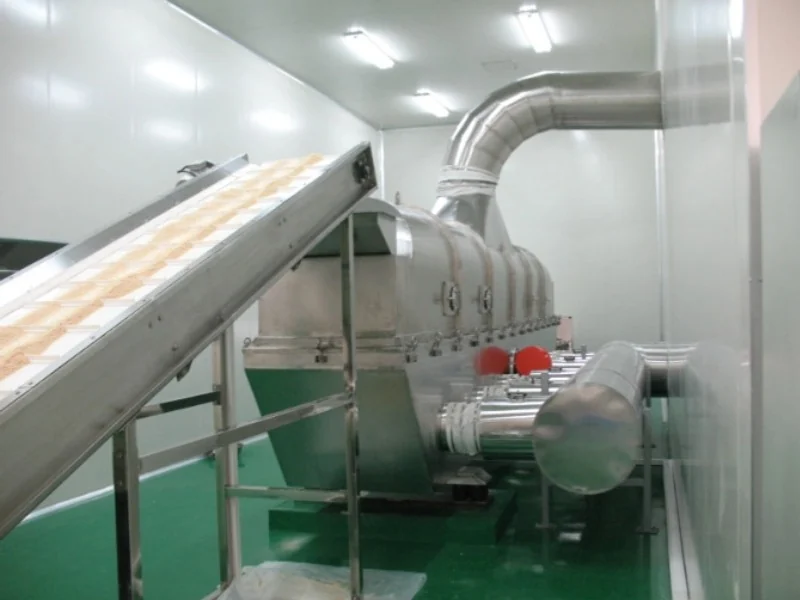
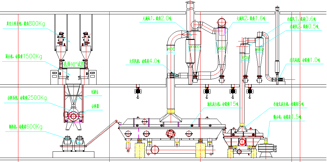
- Flexible process integration: cooling, conveying, screening and, where specified, granulation or limited liquid addition can be incorporated into the process.
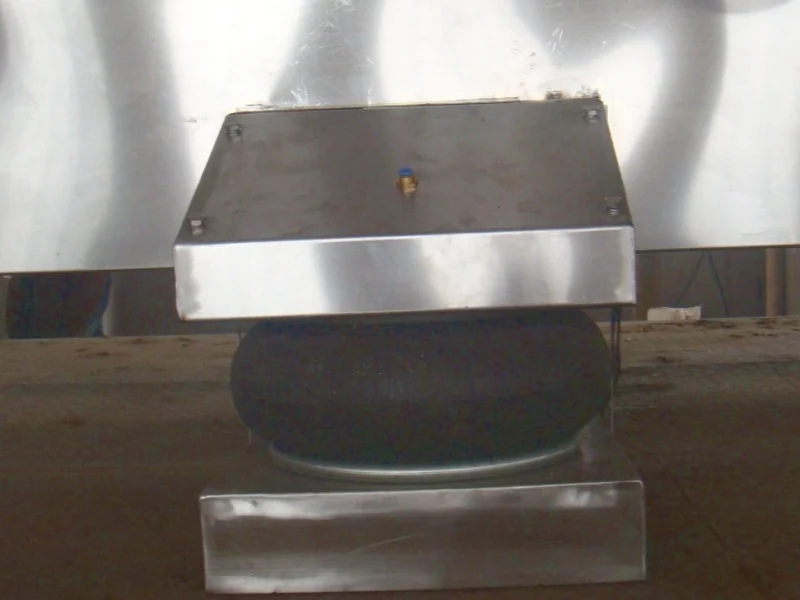
Vibration generates noise and subjects some components to cyclic loading. Vibration isolation, inspection and maintenance requirements should be considered when specifying the installation.
Construction and Configuration Options
- Zoned air supply: separate pre-drying, intensive drying and cooling zones allow conditions to be matched to each stage.
- Cleaning access: quick-release upper and lower housings provide access to the bed and internal surfaces.
- Bottom air inlet: air enters below the bed to support even distribution and reduce system resistance.
- Expanded upper housing: an enlarged exhaust chamber can consolidate exhaust connections and reduce cleaning points.
- Directional distributor plate: a louvered plate can be selected to guide airflow and material movement while limiting material leakage.
- Conditioned cooling air: refrigerated dehumidification can be specified to cool the inlet air and reduce moisture reabsorption during product cooling.

Drying and Cooling Arrangements
Integrated Drying and Cooling
A single bed incorporates drying and cooling sections with separately controlled air supplies. The arrangement is selected to match the required moisture removal and discharge temperature.
Separate Dryer and Cooler in Series
Two fluid bed units can be connected in series, with the first unit used for drying and the second for cooling. Separate units provide flexibility in arranging the two process stages and their air systems.
Typical Applications
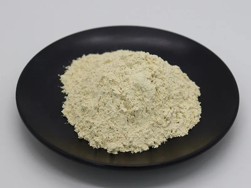
The equipment is suitable for powders and granules that can be fluidized under the selected operating conditions. Material trials help establish the appropriate air supply, temperature and vibration settings.
- Chemicals: catalysts, resins and polymer granules.
- Pharmaceuticals: pharmaceutical granules and vitamin granules.
- Food ingredients: seasonings, food additives, grains and sugars.
- Fertilizers: compound fertilizers and micronutrient fertilizers.
- Minerals: suitable mineral powders and metal oxides.
- Plastics: plastic pellets and masterbatch.
Specify Your Drying Duty
For equipment selection, provide the material name, particle-size distribution, bulk density, feed rate, initial and target moisture, temperature limits and required discharge temperature. Include any requirements for cooling, cleaning, dust collection, feed and discharge equipment, and available installation space.
Selection Questions
Can drying and cooling be combined in one system?
Yes. The described ZLG arrangements include an integrated bed with separate drying and cooling air zones, or two units in series with one dryer and one cooler.
What data is needed for selection?
Provide particle-size distribution, bulk density, feed rate, initial and target moisture, temperature limits, discharge temperature, cooling and cleaning needs, dust collection and installation space.
Related Equipment and Applications
Discuss your material and request an equipment recommendation.