Indirect Drying for Powders, Granules, Filter Cakes and Slurries
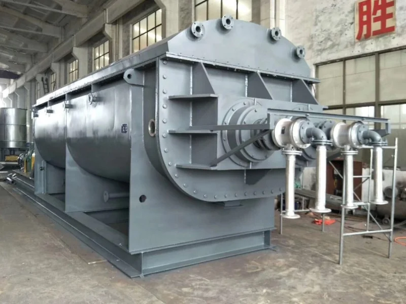
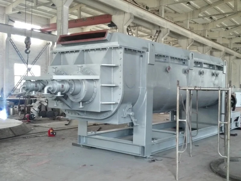
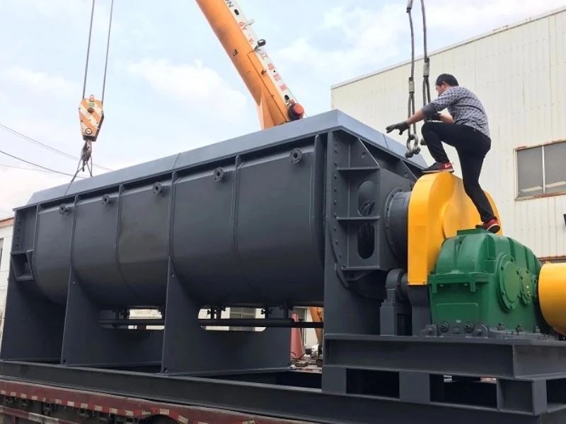
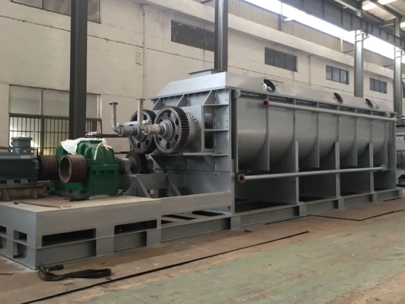
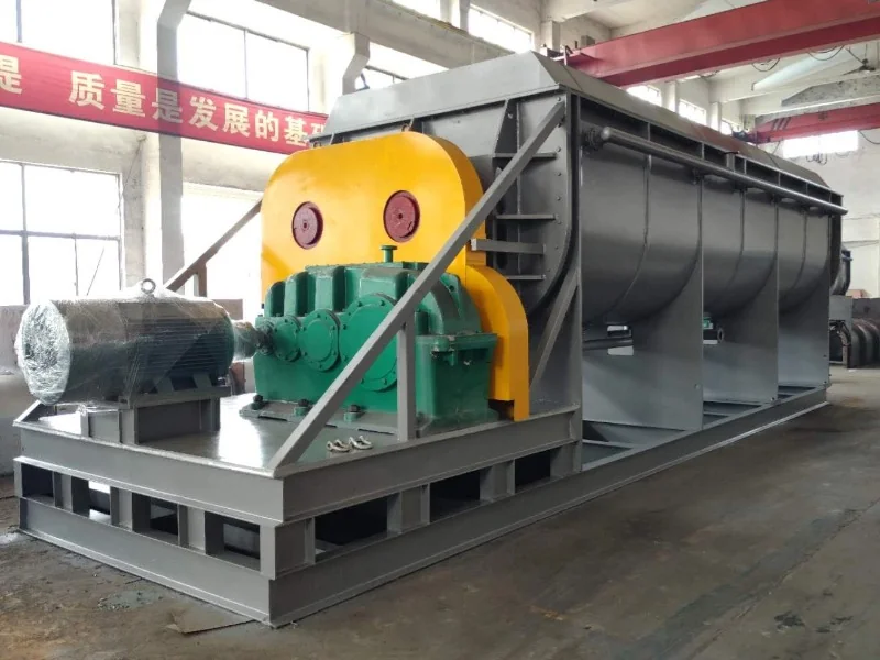
The Longxin KJG hollow paddle dryer removes moisture or solvent through heated metal surfaces while twin paddle shafts agitate the material. It is a horizontal dryer designed primarily for continuous operation, with process configurations selected for the feed and required final product.
Heat is supplied through the vessel jacket, hollow shafts and paddles. Because a large stream of hot air is not needed to deliver the drying heat, the process can reduce the gas volume requiring downstream treatment. A small sweep-gas flow may be used where needed to remove vapor.
Working Principle and Main Structure
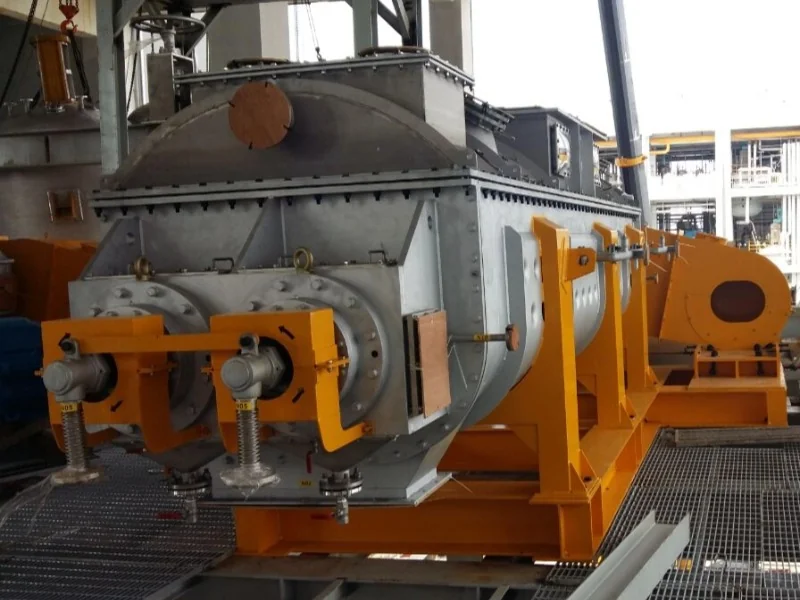
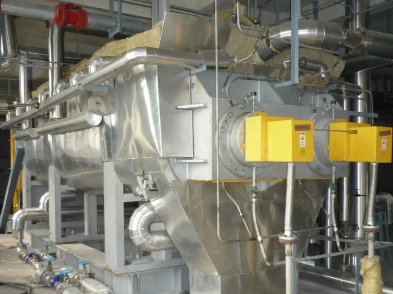
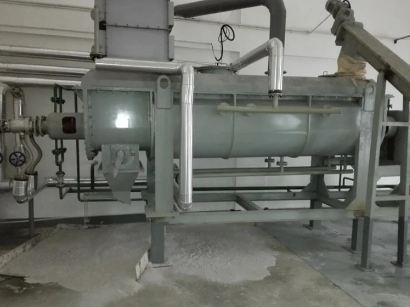
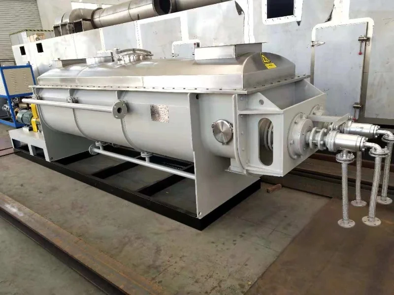
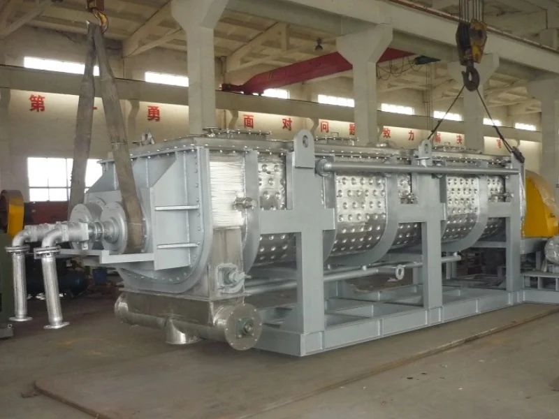
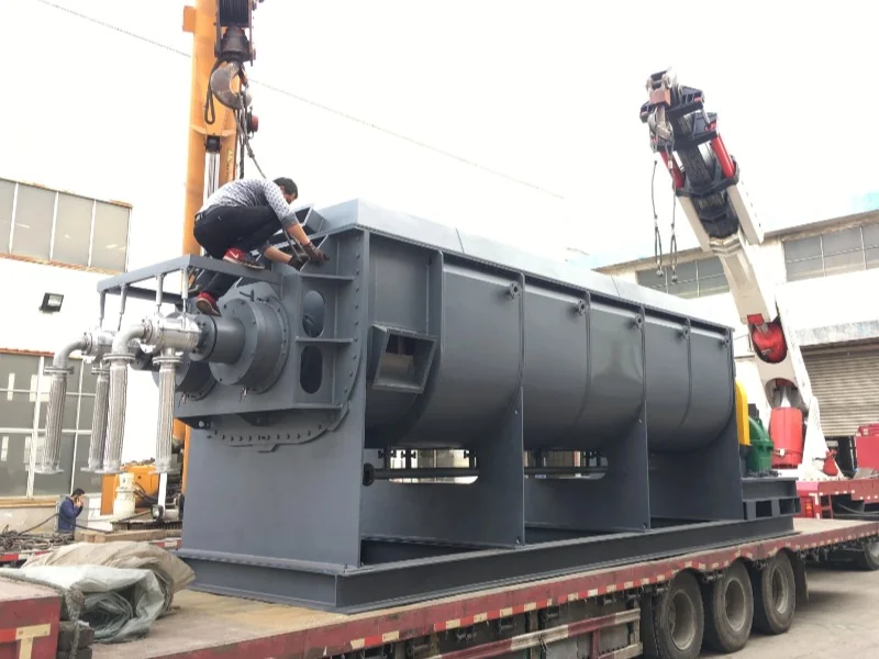
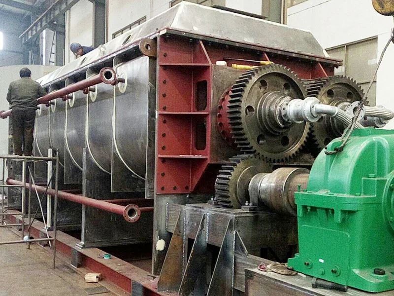
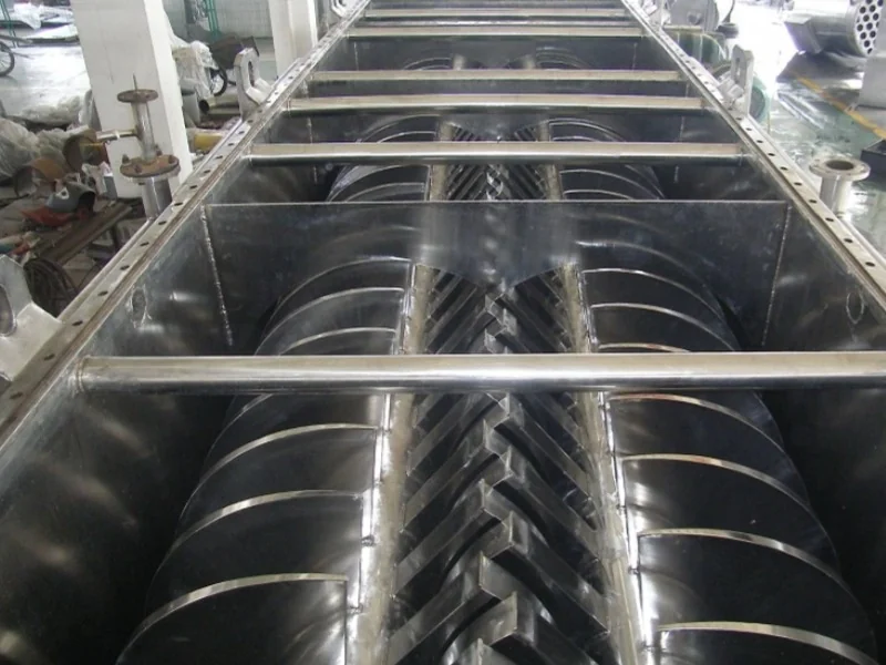
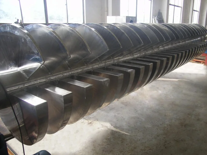
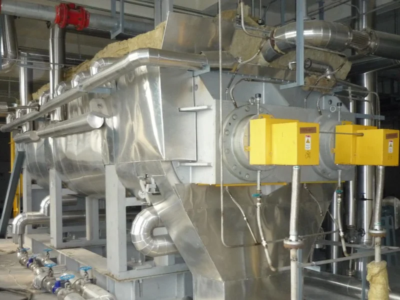
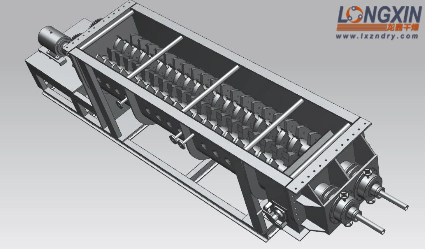
The dryer consists of a jacketed trough with a W-shaped cross-section, a cover, two hollow paddle shafts, end plates, rotary joints, flexible connections and a drive system. Steam, thermal oil or hot water flows through the selected heating circuits without directly contacting the product.
- Feed enters the trough: the inlet arrangement distributes wet material into the working zone.
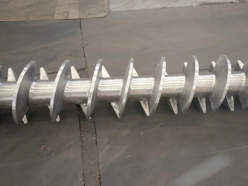
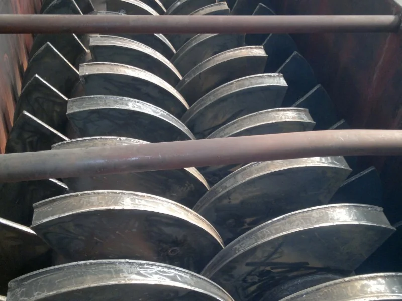
- Paddles mix and transfer heat: closely spaced, wedge-shaped hollow paddles provide heat-transfer area within the material bed.
- Surface contact is renewed: as the paddles rotate, material moves across their inclined faces. Scrapers lift deposits from the bottom of the trough and help limit stagnant zones.
- Vapor is removed: the vapor-handling equipment is selected for the moisture, solvent and operating pressure.
- Product is discharged: the feed, drying and discharge arrangements maintain material flow, with residence time adjusted for the required drying duty.
Key Features
- Efficient use of heating energy: conductive heating reduces the heat carried away by a large drying-air stream. The compact arrangement also limits exposed surface area.
- High heat-transfer area per unit volume: hollow paddles provide substantial heating surface within a compact vessel, helping reduce installation space.
- Flexible thermal operation: steam, thermal oil and hot water can be used for heating. Cooling water or brine can be used when the equipment is configured for cooling.
- Separation of utilities and product: the heating medium remains inside the jacket and rotating heat-transfer surfaces. Steam condensate can be returned through a suitable utility system.
- Agitation for difficult materials: the drive and paddle arrangement can be selected to handle the resistance encountered as wet material passes through a sticky or plastic phase.
- Application-specific shaft speed: rotational speed is selected for the feed behavior, heat-transfer requirement and wear considerations.
- Continuous or batch arrangements: the operating mode, vapor system and discharge arrangement are matched to the process.
Process Arrangements
Atmospheric Drying with Vapor Treatment
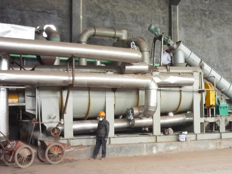
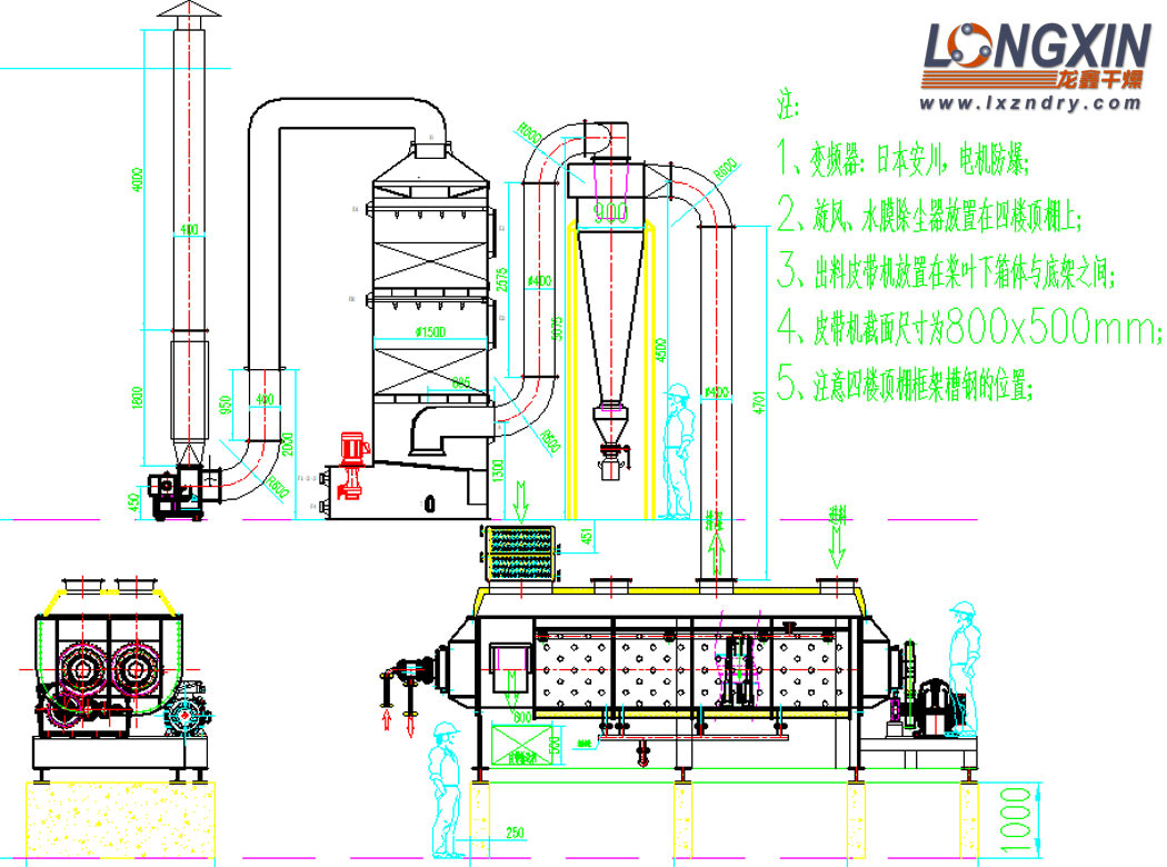
The illustrated atmospheric arrangement connects the paddle dryer to a cyclone, wet scrubber and exhaust fan. The vapor-treatment system is selected for the entrained particles and vapor composition.
Vacuum Drying and Solvent Recovery
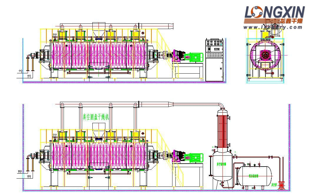
A suitably enclosed dryer can be integrated with condensation, a liquid receiver and a vacuum system when the process calls for reduced-pressure drying or solvent recovery. The equipment configuration is selected for the actual product and solvent.
The reference drawing below illustrates this vapor-handling arrangement on a disc-type vacuum dryer. It shows the condenser, receiver and vacuum pump; the KJG twin-paddle structure is shown separately above.
Paddle and Disc Dryers in Series
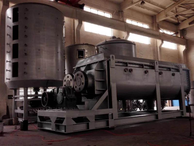
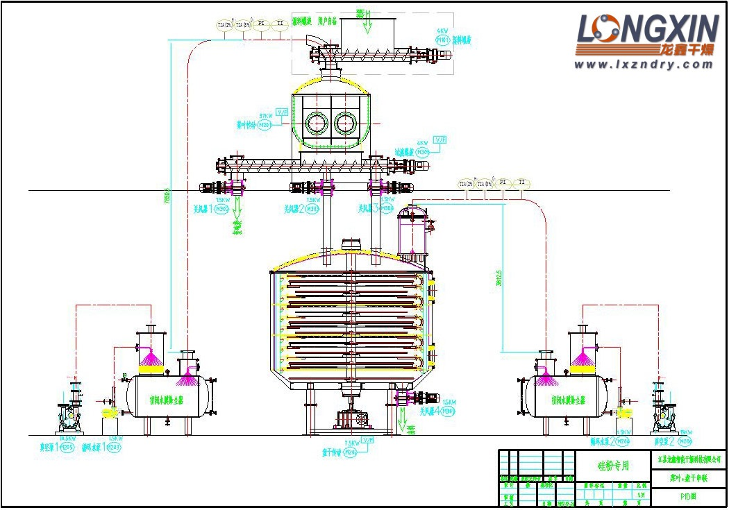
A paddle dryer can be combined with a vertical disc dryer for staged material treatment. The supplied process drawing shows feeding, transfer between stages and the associated vapor systems. The gallery also includes a photograph of an installed line.
Applications Beyond Drying
- Drying: powders, granules, filter cakes and slurries in chemical, petrochemical, dye, food, pharmaceutical, agrochemical and industrial sludge applications.
- Cooling: soda ash, titanium dioxide, ferronickel alloy powders and other suitable particulate materials, using an appropriate cooling medium.
- Low-temperature calcination: suitable duties include converting calcium sulfate dihydrate to hemihydrate and sodium bicarbonate to soda ash.
- Heating and melting: indirect heat transfer and mixing can be used for suitable thermal treatment duties.
- Reaction and heat treatment: selected compound-fertilizer, modified-starch and food-processing applications can use the unit for controlled heating and mixing.
For heat-sensitive, oxidation-sensitive or flammable materials, the operating temperature, pressure, atmosphere and vapor-recovery equipment are specified for the application. Food sterilization and other product-critical heat treatments require a process matched to the required temperature and residence time.
Equipment and Component Gallery
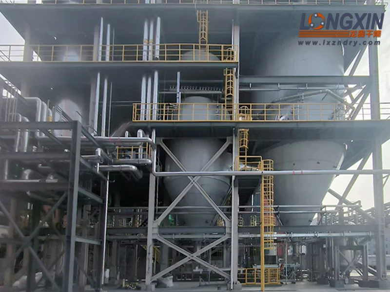
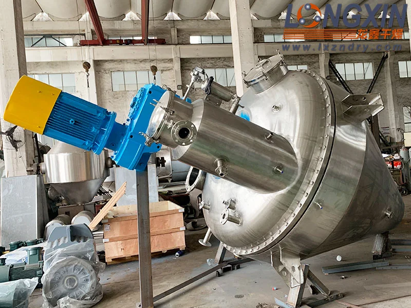
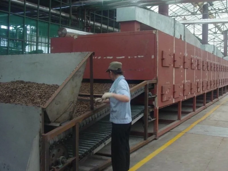
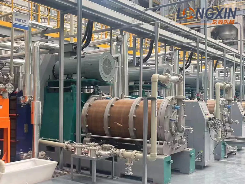
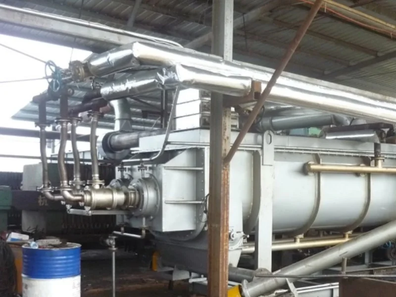
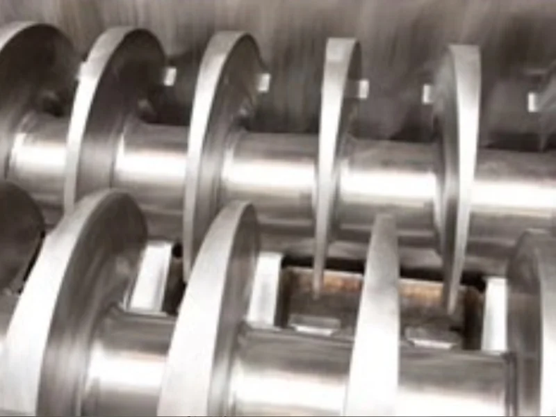
The gallery includes atmospheric and vacuum paddle dryers, installations identified as KJG-15 through KJG-260, a paddle-and-disc drying line, and five views of paddle shafts and internal assemblies. The model labels identify the photographed equipment; they do not by themselves specify throughput.
Select a Paddle Dryer for Your Material
Provide the material composition, feed rate, initial and final moisture or solvent content, bulk density, particle size, viscosity and behavior through the sticky phase. Include the allowable product temperature, heating utilities, operating pressure, vapor-treatment or solvent-recovery requirements, contact-material specification and available installation space.
Selection Questions
Which heating media can a KJG paddle dryer use?
The described heating circuits can be supplied with steam, thermal oil or hot water. The medium remains inside the jacket and hollow rotating components rather than directly contacting the product.
Can the dryer be specified for solvent recovery?
A suitably enclosed configuration can be integrated with condensation, a receiver and vacuum equipment when the product and solvent require reduced-pressure drying or recovery.
Related Equipment and Applications
Discuss your material and request an equipment recommendation.